[Updated: Clarified what I wrote about the way stacks in AVR work, in the Push/Pop section.]
Data Transfer Instructions
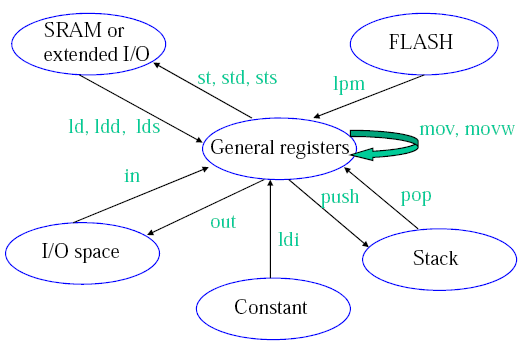
(Credit: Hui Wu/COMP2121 Lecture Notes)
Load Direct (ld):
ld Rd, v
Rd $latex \in$ {r0, r1, ..., r31} and v $latex \in$ {x, x+, -x, y, y+, -y, z, z+, -z}
(remember the X, Y, Z pointers)
Load Program Memory (lpm):
Can take on three forms,
| Syntax |
Operation |
lpm
|
R0⟵(Z)
|
lpm Rd, Z
|
R0⟵(Z)
|
lpm Rd, Z+
|
Rd⟵(Z)
Z⟵Z+1
|
Z contains the byte address while the program flash memory uses word addressing. Therefore the word address must be converted into a byte address before having access to the data on the program flash memory. Example usage, (Table_1<<1 converts the word address into a byte address)
   ldi zh, high(Table_1<<1) ; Initialise Z pointer
   ldi zl, low(Table_1<<1)
   lpm r16, z+ ; r16=0x76
   lpm r17, z ; r17=0x58
   ...
Table_1: .dw 0x5876
   ..
IN/OUT:
AVR has 64 IO registers. Example,
in Rd, A
out A, Rd
where 0 ≤ A ≤ 63.
Push/Pop:
The stack pointer (implemented as two 8-bit registers in the I/O space) points to the next free space in RAM above/below (depends how you look at it) the stack. The stack in AVR is part of the SRAM space, and the stack (in AVR) grows from higher memory locations to lower memory locations. I'm talking about the actual value of the address, so 0xFFFF is a higher address than 0xDDDD. This got me a little confused at one stage because if you draw a picture of memory with 0x0000 at the top of the diagram, and 0x0001 below it and so on then in reference to the diagram a stack that is getting larger with PUSH operations is growing upwards (you usually associate higher to lower with down, this is why I got confused).
So the first thing you must do is initialise the stack pointer (RAMEND is a good starting location).
So a push operation,
push Rr
will push Rr onto the stack (ie. put the contents of Rr into the location that the SP points to), and then decrement the SP by 1. Pop has a similar opposite effect.
Shift Instructions
Logical shift left
lsl Rd
 Rotate Left Through Carry
rol Rd

Both operation change some status register flags.
Functions
We dabbed into this in first year but just to revise and extend a little I'll try to reiterate this here.
The heap is used for dynamic memory applications (eg. malloc()).
The stack is used to store return addresses, parameters, conflict registers and local variables and other things.
In passing parameters in WINAVR (C compiler for AVR) for say a function call they are passed by value for scalar variables (eg. char, int, float) and passed by reference for non-scalar variables (eg. array, struct).
Rules are needed between the caller and the callee to resolve issues such as,
- how to pass values and references to a function?
- where to get the return value?
- how to handle register conflicts? (if a function wants to use a register that was previously in use)
- how to allocate and deallocate stack memory to and from local variables?
If a register is used in both caller and callee and the caller needs its old value after the return from the callee, then a register conflict occurs. Either the compiler or the assembly programmer needs to check for this. The work around is to save the conflict registers on the stack.
The return value of a function needs to be stored in designated registers. WINAVR uses r25:r24 for this.
A stack consists of stack frames. A stack frame is created whenever a function is called, and it is freed whenever the function returns.
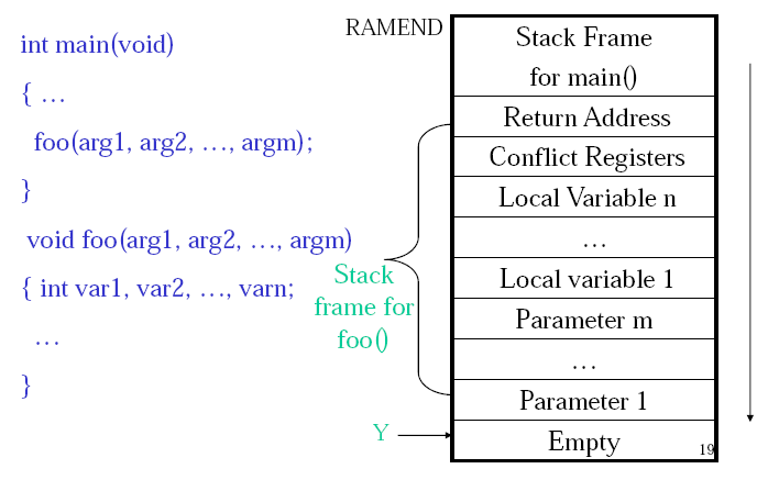
(Credit: Hui Wu/COMP2121 Lecture Notes)
Macros
The AVR assembler offers macros. A macro is just a segment of code that you define and can then use by just calling the macro. Basically the macro name is just a place holder for the macro code. When the program is assembled the macro name will be replaced by the code that macro defines. This defines a macro named mymacro,
.macro mymacro
 lds r2, @0
 lds r3, @1
 sts @1, r2
 sts @0, r3
.endmacro
We can then invoke this macro with,
mymacro p, q
The p, q are used like arguments. So @0 will be replaced with p and @1 will be replaced by q. In AVR you can used @0 up to @9 in the macro body.
Assembly Process
The AVR assembler uses a two pass process.
Pass One:
- Lexical and syntax analysis: checking for syntax errors.
- Record all symbols (labels...) in a symbol table.
- Expand macro calls.
Pass Two:
- Use symbol table to substitute the values for the symbols and evaluate functions (eg. low(-13167)).
- Assemble each instruction (ie. generate machine code). For example add Rd, Rr is encoded as machine code as 0000 11rd dddd rrrr.
References
Wu, Hui. COMP2121 09s1 Lecture Notes.
