Back in 2007 I developed a software tool that could generate technical drawings in a range of drawing projections from a 3D model with emphasis on oblique (both cabinet and cavalier, as well as custom obliques), planometric, dimetric, trimetric and one-point perspective.
I could describe them all as well as many more in terms of what the projected three axis look like on the projection plane. I described them all in terms of a scale on each of the three axis, as well as the angle two of the axis make with the projection plane's horizontal.
[caption id="attachment_130" align="aligncenter" width="151" caption="Description of the projection in terms of the projected view of the three standard basis."]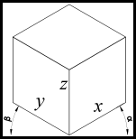 [/caption]
In terms of the actual development of the program I'm sure I could have done things a lot better. But I did learn a lot from the experience. The program worked to my needs and did what I wrote it to do so in that sense it was a success. The only downside would be that I did a lot of code rewriting of code that already existed out there (which probably did thinks better than I implemented them). Although since then I have done much more programming and had formal training so have learnt about better methods and practices.
The approach I took was basically import a DXF file, process the data to change its projection, and then export it as a DXF again. I used 3D polylines generated from my 3D model in Rhino and saved as DXF for the input. So I had to write a cutdown DXF reader/writer, as well as a way of storing this data internally and then doing the transformations on it then exporting it back into DXF so I could open it up in AutoCAD.
I only supported points, polylines, circles and arcs as this is basically all that Rhino exported from my model. To simplify the process of circles and arcs I internally converted them to a bunch of polylines as only for some projections they stayed as nice ellipses.
[caption id="attachment_104" align="aligncenter" width="961" caption="The user interface of the tool."]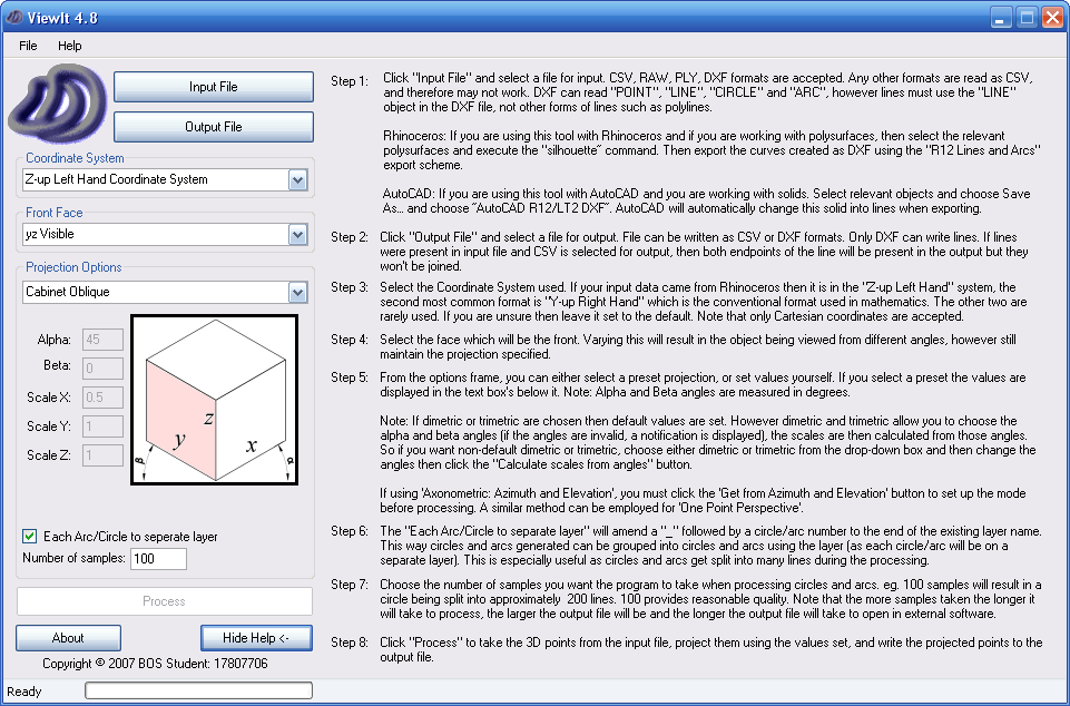 [/caption]
From a very simple model in Rhino, I use the silhouette tool to create the polylines which once impororted into my program produced the following samples.
[caption id="attachment_131" align="aligncenter" width="152" caption="Cabinet Oblique"]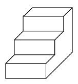 [/caption]
[caption id="attachment_132" align="aligncenter" width="205" caption="Cavalier Oblique"]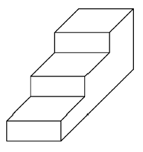 [/caption]
[caption id="attachment_133" align="aligncenter" width="184" caption="Planometric"]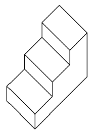 [/caption]
[caption id="attachment_134" align="aligncenter" width="180" caption="One Point Perspective"]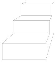 [/caption]
There is also a range of built in axonometric projections...
[caption id="attachment_105" align="aligncenter" width="450" caption="A range of axonometric projections are built in."]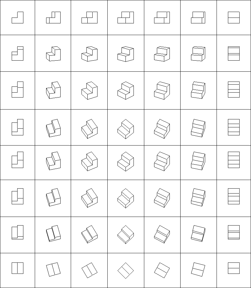 [/caption]
Finally here are some of my production drawings (from my 2007 HSC ITG Major Work (photos here)) that I used the software to create.
[caption id="attachment_135" align="aligncenter" width="450" caption="Oblique"]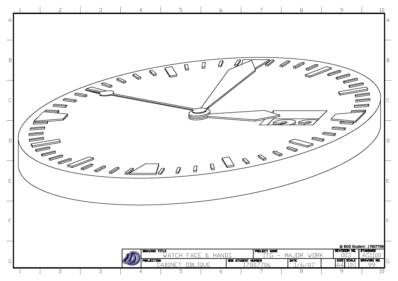 [/caption]
[caption id="attachment_136" align="aligncenter" width="450" caption="One Point Perspective"]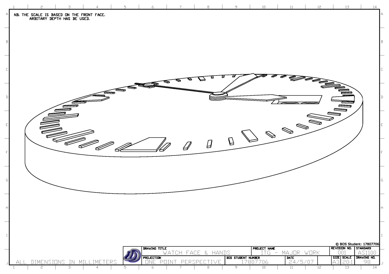 [/caption]
[caption id="attachment_137" align="aligncenter" width="450" caption="Planometric"]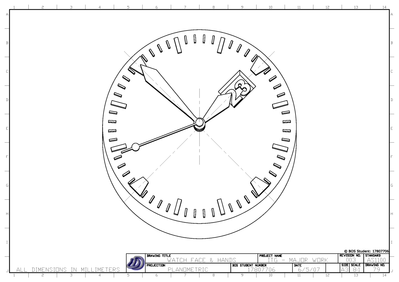 [/caption]
[caption id="attachment_138" align="aligncenter" width="450" caption="Trimetric"]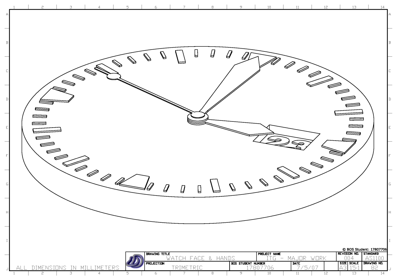 [/caption]