avatar tianjara.net | blog icon Andrew Harvey's Blog

Entries tagged "comp2121".

COMP2121 Quick Summary on Particular Aspects
23rd June 2009

Von-Newman vs. Harvard Architecture.

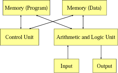
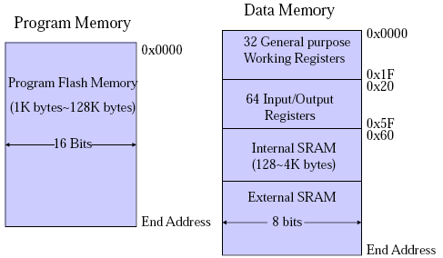
Von-Newman has a single memory space, share for data and program instructions. Harvard Architecture has separate memory spaces for data and instructions (so you cannot execute from the data memory).

2's compliment

twos_compliment

It is important to know that the hardware does all arithmetic in 2's compliment. It is up to the programmer to interpret the number as signed or unsigned.

To convert a number from 2's compliment, for example -45 in 2's compliment is 11010011, we can do something like this,

$latex 1 \times (-2^7) + 1 \times 2^6 + 1 \times 2^6 + 0 \times 2^5 +1 \times 2^4 + 0 \times 2^3 + 0 \times 2^2 + 1 \times 2^1 + 1 \times 2^0 = -45$

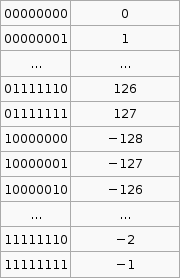
To go the other way from say -1 to the 2's compliment form 11111111 we use that $latex 2^p - X$ formula. I'm not exactly sure how its supposed to work so I've hacked it to make it work.

If the number you wish to convert is negative, let $latex X = -n$, so that X is positive then take $latex 2^p$ where p is the number of bits you are using (say 8), then subtract X. If the number to convert is less than $latex 2^p$ (where p is the number of bits, say 8 ) then leave it as is and that in your 2's compliment.

Now that was complicated. But its the only way I can get that advertised $latex 2^p - X$ formula to work with the given set of sample data (as in that table above).

Sign Extension

Why do we need sign extension? We need it in order to do operations on numbers than have different bit lengths (the number of bits used to represent the number).

Decimal to Binary

From a human kind of approach to convert 221 to binary, we see that $latex 2^7 = 128$, that is 7 is the largest power of 2 less than 221, so we have $latex 1 \times 2^7$. That gives us 128, so we still have 93 (221-128) to go. We try $latex 2^6$, this is less than 93. So far we have $latex 1 \times 2^7 + 1 \times 2^6$. 29 left now, but $latex 2^5$ is greater than 29, so we put a zero in that digit, ie. $latex 1 \times 2^7 + 1 \times 2^6 + 0 \times 2^5$. If we go on we get $latex 1 \times 2^7 + 1 \times 2^6 + 0 \times 2^5 + 1 \times 2^4 + 1 \times 2^3 + 1 \times 2^2 + 0 \times 2^1 + 1 \times 2^0$. Taking the coefficients of the $latex \times 2^x$ terms we get the number 221 in binary, 11011101.

We can convert hexadecimal to binary by going from hex to decimal then decimal to binary. For hex to decimal,

$latex \mbox{F23AC} = 15 \times 16^4 + 2 \times 16^3 + 3 \times 16^2 + 10 \times 16^1 + 12 \times 16^0 = 992172$ (where F23AC is in hex and 992172 is in decimal)

Operations on Signed and Unsigned Multi byte Numbers

add al, bl
adc ah, bh
does a + b, result in is a.

There are 3 multiplication operations, MUL (Multiply Unsigned), MULS (Multiply Signed) and MULSU (Multiply Signed with Unsigned). They each do this. Notice the result is stored in r1:r0.

mulThus to do n*m = r where n is 2 bytes unsigned and m is 1 byte signed,
mulsu nl, m ;nl * (signed)m
movw rh:rl, r1:r0
mulsu nh, m ;(signed)nh * m
add rh, r0

We can also do 16bit * 16bit,

;* From AVR Instruction Set Guide, pg 99-100.
;* Signed multiply of two 16-bit numbers with 32-bit result.
;* r19:r18:r17:r16 = r23:r22 * r21:r20
muls16x16_32:
clr r2
muls r23, r21 ;(signed)ah * (signed)bh
movw r19:r18, r1:r0
mul r22, r20 ;al * bl
movw r17:r16, r1:r0
mulsu r23, r20 ;(signed)ah * bl
sbc r19, r2
add r17, r0
adc r18, r1
adc r19, r2
mulsu r21, r22 ;(signed)bh * al
sbc r19, r2
add r17, r0
adc r18, r1
adc r19, r2
ret

brge and brsh

Calculating Total Stack Space Needed

Draw a call tree, find the path with the most total weight, that total weight is the total stack size needed. Here is the sample question,

A C program consists of five functions. Their calling relations are shown as follows (the arguments and irrelevant C statements are omitted).

int main(void) {

  func1(…);
  func2(…);

}
int func1(…) {
  …
  func1(…);
  …
}

int func2(…) {
  …
  func3(…);
  func4(…);
  …
}

func1() is a recursive function and calls itself 15 times for the actual parameters given in main(). Both func3() and func4() do not call any function. The sizes of all stack frames are shown as follows.

main(): 200 bytes. func1(): 100 bytes. func2(): 400 bytes. func3(): 1,400 bytes. func4(): 300 bytes. How much stack space is needed to execute this program correctly? (3 marks)
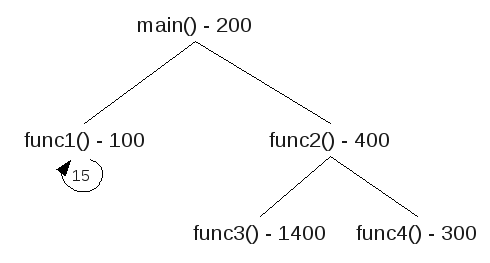
call_graphThere are three paths,
main() func1() func1() x 15 200+100+15x100 =1800 main() func2() func3() 200+400+1400 =2000 main() func2() func4() 200+400+300 =900
The path with the most total weight is main() > func2() > func3(), so this is the total stack space needed.

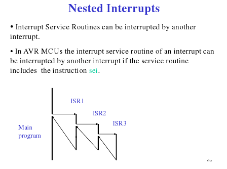
Nested Interrupts

nested_interrupt(Source: Hui Wu's Lecture Notes)

Keypads with 'abc' 'def' ... buttons

These keypads where to enter b you need to press the abc button twice in succession, but wait to long at it will chose a. Here is a psudo algorithm that seemed to fit this,

.def reg = rN
.def reg = rM
.def count = rX

//passvalue means that we register the given value ie. abc abc wait > b

setup:
clr reg (to some value that is != to a key value) ;set to default
clr count
rjmp keyloop

keyloop:
  check pins for a key
  if no key pressed rjmp keyloop, else continue

  //key was pressed, and value is stored in key
  reset someTimeCounter
  if (key == reg) {
     inc count
     if (count == 3)
        passvalue(reg,count)
  }else{
     if (reg != default) ;so we don't initially passvalue
        passvalue(reg,count) ;send the last value
     reg = key ;store the new one
     count = 1
  }

rjmp keyloop

if someTimeCounter expires and count != 0 //(count up, so expires after time to wait for anymore keypresses) (check count != 0, because if its 0 then we never had any key pressed that we need to send)
   passvalue(reg,count)
   reg = default

Switch Bounce Software Solution

When a switch makes contact, its mechanical springiness will cause the contact to bounce, or make and break, for a few millisecond (typically 5 to 10 ms). Two software solutions are wait and see and counter-based.

  1. If we detect it as closed, wait for a little bit and check again.
  2. Poll the switch constantly. For each poll if the switch is closed increment the counter. If we reach a certain value in a certain time then the switch was closed (or button pressed).

Serial Communication (Start and Stop bit)

"[The] start bit is used to indicate the start of a frame. Without the start bit, the receiver cannot distinguish between the idle line and the 1 bit because both are logical one. A stop bit is used to allow the receiver to transfer the data from the receive buffer to the memory." (Wu, Homework 6 Solutions)

UART
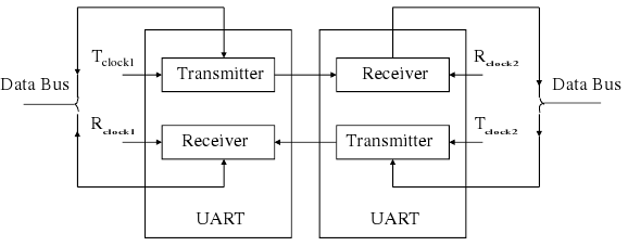
uart(Source: Hui Wu, Lecture Notes)

Sample Q3a

(This code probably won't work and probably has errors (and maybe not just simple ones, but serious ones that mean that the logic is wrong))

.dseg
A: .byte 20 ;array of size 10, element size 2 bytes

.cseg
ldi XL, low(A)
ldi XH, high(A)

;add the contents of the array.
store 0
store 1
store 2
store 3
store 4
store 5
store 6
store 7
store 8
store 9

;find the largest value
ldi XL, low(A)
ldi XH, high(A)

;start with the 1st element of the array
ld r25, X+
ld r26, X+

ldi r20, 10 ;size of array
loop:
 cpi r20, 0
 breq endloop

 ld r21, X+
 ld r22, X+

 cp r25, r21
 cpc r26, c22
 brlo lowerthan
 ;we have a new max
 mov r25, r21
 mov r26, r22

 lowerthan:

 inc r20
 rjmp loop
endloop: rjmp endloop

.macro store
ldi r16, low(@0)
ldi r17, high(@0)

st X+, r16
st X+, r17
.endmacro

For some reason in my lecture notes I have "eg. fine 2nd or 3rd smallest or largest" so here is a modification to do something like that.

.dseg
A: .byte 20 ;array of size 10, element size 2 bytes

.cseg
ldi XL, low(A)
ldi XH, high(A)

;add the contents of the array.
store 0
store 1
store 2
store 3
store 4
store 5
store 6
store 7
store 8
store 9

;sort into accending
loopthough for the length of array, (by then we can be sure its sorted)
ldi r23, 10
largeloop:
 cpi r23, 0
 breq endlargeloop

 ;point X to the start of A
 ldi XL, low(A)
 ldi XH, high(A)

 ;start with the 1st element of the array
 ld r25, X+
 ld r26, X+

 ldi r20, 10 ;size of array
 loop:
 cpi r20, 0
 breq endloop

 ;the next value
 ld r21, X+
 ld r22, X+

 cp r25, r21
 cpc r26, c22
 brge gethan
 ;r22:r21 < r26:r25
 ;swap the order
 st -X, r26
 st -X, r25
 st -X, r22
 st -X, r21

 ld r24, X+ ;to change the X pointer
 ld r24, X+

 ld r25, X+
 ld r26, X+

 gethan:

 inc r20
 rjmp loop
 endloop:
endlargeloop:

inf: rjmp inf

.macro store
ldi r16, low(@0)
ldi r17, high(@0)

st X+, r16
st X+, r17
.endmacro
Tags: comp2121, computing.
COMP2121 - Wk05 - Interrupts
20th June 2009

To explain interrupts, Wu used an example of a network card that is downloading a file. The network card has a buffer, and only once this buffer is full (or data stream is complete) should the CPU then copy the contents from the buffer to the RAM. So how does the CPU know when the network card's buffer is full and when to execute the copy? He described two ways here interrupt and polling.

Polling involves the CPU periodically asking the network card, are you full? Two problems with this method are a) there may be a delay as you have to wait for the poll request to be made and b) it wastes a lot of CPU time. Polling is implemented in software, not hardware.

An alternative to polling is using interrupts whereby the network card will send an interrupt signal to the CPU to get its attention. This needs special hardware to implement, however it is very efficient compared with polling.

An interrupt system must (among other things),

IRQ is an interrupt request signal.

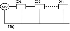
A daisy chain arrangement (as seen below) allows multiple devices to send and IRQ. However the CPU cannot determine from the IRQ line which device sent the interrupt. So in a daisy chain system when the CPU receives an IRQ, it will send a signal to IO1 asking "did you send the IRQ?" if IO1 sent the request it will reply "yes", if not it will pass the question on to the next IO device and so on. The response is passed back in the same way.

daisyChain

Reset is an interrupt in AVR, and in the AVR Mega64 there are five different sources of reset. There is a flag in the MCU Control Register for each of these and can be used to determine the source of a reset interrupt. The watchdog timer is one source of reset.

Watchdog Timer

The watchdog timer is used to try to reset the system if an error such hang occurs. The watchdog timer in AVR can be enabled or disabled.

If the Watchdog timer is enabled, it needs to be periodically reset using the wdr instruction. When (if) the Watchdog times out, it will generate a short reset pulse.

Tags: comp2121, computing.
Setting Up the COMP2121 AVR Board at Home on a Linux Machine
8th May 2009

Just quickly because I need to get back to work, here is how I managed to finally set up a working environment to use the COMP2121 AVR Board at home using linux.

  1. Installed Sun's Virtual Box.
  2. Downloaded and installed Windows 7 Beta (Because its free (as in free beer) and only expires after this course is over)
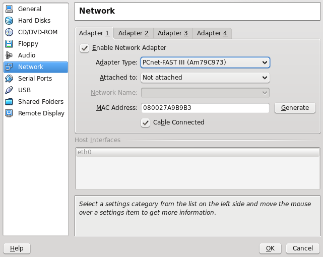
  3. Under the network settings for the Windows 7 virtual machine, disabled it from the rest of the world (I don't need it here, so save my download for better things that Windows updates). Virtual Box Network Settings
  4. Install AVR Studio.
  5. Install a driver (I used this one http://www.ftdichip.com/Drivers/CDM/CDM%202.04.16.exe) from here http://www.ftdichip.com/Drivers/VCP.htm. Don't need to worry about trusting anything as this virtual will just be used for the AVR board.
  6. In the bottom right hand of the virtual box window enable the "FTDI USB <->UNSW uLab" USB device (when its plugged in).
  7. Run nite.exe with these arguments " -l com3 -f 4 -t 1 -h X:\AVRProj\". You may need to check if its com3 or something else in "Device Manager". Where that last path is the default directory (I set up a shared directory in the VM settings).
Tags: avr, comp2121.
COMP2121 - Wk03/04 - Data Transfer/Functions
17th April 2009

[Updated: Clarified what I wrote about the way stacks in AVR work, in the Push/Pop section.]

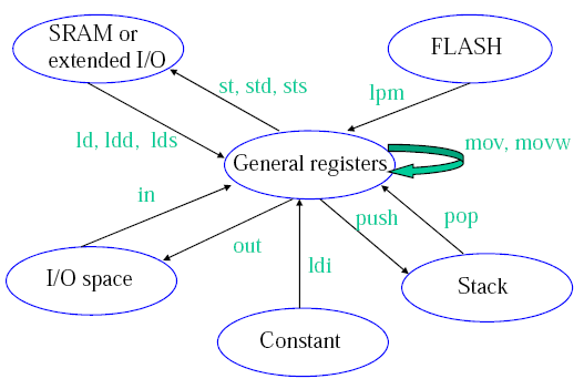
Data Transfer Instructions

datatransfer

(Credit: Hui Wu/COMP2121 Lecture Notes)

Load Direct (ld):

ld Rd, v
Rd $latex \in$ {r0, r1, ..., r31} and v $latex \in$ {x, x+, -x, y, y+, -y, z, z+, -z}

(remember the X, Y, Z pointers)

Load Program Memory (lpm):

Can take on three forms,

Syntax Operation
lpm
R0⟵(Z)
lpm Rd, Z
R0⟵(Z)
lpm Rd, Z+
Rd⟵(Z)
Z⟵Z+1

Z contains the byte address while the program flash memory uses word addressing. Therefore the word address must be converted into a byte address before having access to the data on the program flash memory. Example usage, (Table_1<<1 converts the word address into a byte address)

   ldi zh, high(Table_1<<1) ; Initialise Z pointer
   ldi zl, low(Table_1<<1)
   lpm r16, z+ ; r16=0x76
   lpm r17, z ; r17=0x58
   ...
Table_1: .dw 0x5876
   ..

IN/OUT:

AVR has 64 IO registers. Example,

in Rd, A
out A, Rd
where 0 ≤ A ≤ 63.

Push/Pop:

The stack pointer (implemented as two 8-bit registers in the I/O space) points to the next free space in RAM above/below (depends how you look at it) the stack. The stack in AVR is part of the SRAM space, and the stack (in AVR) grows from higher memory locations to lower memory locations. I'm talking about the actual value of the address, so 0xFFFF is a higher address than 0xDDDD. This got me a little confused at one stage because if you draw a picture of memory with 0x0000 at the top of the diagram, and 0x0001 below it and so on then in reference to the diagram a stack that is getting larger with PUSH operations is growing upwards (you usually associate higher to lower with down, this is why I got confused).

So the first thing you must do is initialise the stack pointer (RAMEND is a good starting location).

So a push operation,

push Rr

will push Rr onto the stack (ie. put the contents of Rr into the location that the SP points to), and then decrement the SP by 1. Pop has a similar opposite effect.

Shift Instructions

Logical shift left

lsl Rd

lslRotate Left Through Carry

rol Rd

rol

Both operation change some status register flags.

Functions

We dabbed into this in first year but just to revise and extend a little I'll try to reiterate this here.

The heap is used for dynamic memory applications (eg. malloc()).

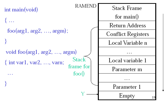
The stack is used to store return addresses, parameters, conflict registers and local variables and other things.

In passing parameters in WINAVR (C compiler for AVR) for say a function call they are passed by value for scalar variables (eg. char, int, float) and passed by reference for non-scalar variables (eg. array, struct).

Rules are needed between the caller and the callee to resolve issues such as,

If a register is used in both caller and callee and the caller needs its old value after the return from the callee, then a register conflict occurs. Either the compiler or the assembly programmer needs to check for this. The work around is to save the conflict registers on the stack.

The return value of a function needs to be stored in designated registers. WINAVR uses r25:r24 for this.

A stack consists of stack frames. A stack frame is created whenever a function is called, and it is freed whenever the function returns. avrstack

(Credit: Hui Wu/COMP2121 Lecture Notes)

Macros

The AVR assembler offers macros. A macro is just a segment of code that you define and can then use by just calling the macro. Basically the macro name is just a place holder for the macro code. When the program is assembled the macro name will be replaced by the code that macro defines. This defines a macro named mymacro,

.macro mymacro
 lds r2, @0
 lds r3, @1
 sts @1, r2
 sts @0, r3
.endmacro

We can then invoke this macro with,

mymacro p, q

The p, q are used like arguments. So @0 will be replaced with p and @1 will be replaced by q. In AVR you can used @0 up to @9 in the macro body.

Assembly Process

The AVR assembler uses a two pass process.

Pass One:

Pass Two:

References

Wu, Hui. COMP2121 09s1 Lecture Notes.

Tags: avr, comp2121, computing.
COMP2121 - ADD and ADC
14th April 2009

Just some notes on using ADD and ADC (and also a not on compare and branch instructions at the end). (Thanks also to my lab partner who helped me with some of this stuff.)

The registers for AVR are 8 bits long, as noted if I want to store a 16 bit number I need to use two registers, one will store the low byte and the other will store the high byte. eg the 16 bit binary number a = 1111111100000000 (as big endian) would be stored as a_high = 11111111, a_low = 00000000.

Another thing that I've learnt is how addition of multi byte numbers in AVR works. AVR has the instructions ADD (add without carry) and ADC (add with carry). Lets look at a simple case first.

ldi r16, 0b10101010 //the 0b indicates binary ($ or 0x for hex, nothing for decimal, 0 for octal). loads the binary number 10101010 into register 16.
ldi r17, 0b10101010
add r16, r17

What happens here is,

  10101010
+ 10101010
  01010100
  c c c c

The carry bit is set, and hence and overflow has occurred. The actual answer is 101010100 but this has 9 bits and cannot fix in the 8 bits of space we have for the result to be stored into r16. Here we used the ADD instruction this means (at least to the best of my understanding, please correct me if I'm wrong) that we ignore what is originally in the carry flag (part of the status register). If we used ADC and the carry flag was set to 1 then when we add the right most bit as above 0+0 = 0 but we have a carry so we would get a 1 in that last bit. We can use this to do multi byte arithmetic.

Say we have,

//a is a 16 bit number 1010101010101010
ldi al, 0b10101010
ldi ah, 0b10101010
//b is a 16 bit number 1010101010101010
ldi bl, 0b10101010
ldi bh, 0b10101010

//to do a+b (and store the result in a) we do
add al, bl
adc ah, bh

We can then extend this to as many bytes as we want. Say we have a 3 byte number spread over the registers of a_0, a_1, a_2 and another 3 byte number in the registers b_0, b_1, b_2. We could add them like this,

add a_0, b_0
adc a_1, b_1
adc a_2, b_2

The result would be spread over a_0, a_1 and a_2 (remember though that we can still overflow this).

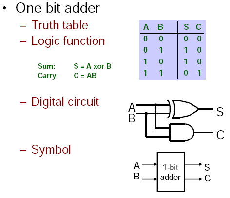
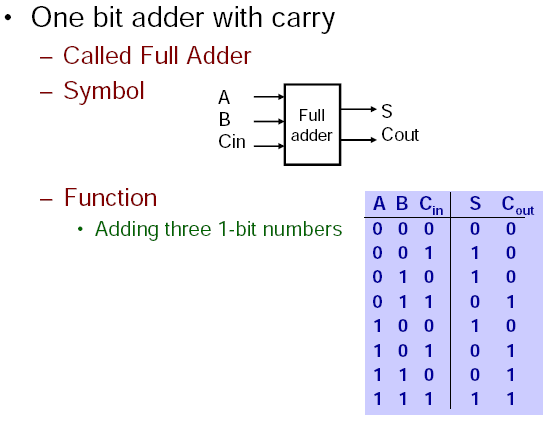
It was also enlightening (though also a nice reminder) to see how this low level addition works. (when doing 1bit addition (without carry), a + b, the sum = a xor b and the carry = a and b.) (see picture below)

onebitadderonebitadderwithcarry(Credit: Annie Guo, Basics of Digital Systems, COMP2121 Notes)

This concept can similarly be applied to other instructions. For example,

cp a, b
breq label

will compare a and be and branch to the label label if a is equal to b (and if not continue on executing the subsequent instructions). However what if you wanted to compare if a two byte number was equal to a two byte number? Sure you could just repeat the code one time for the low byte and another for the high byte but you can also do this,

cp al, bl
cpc ah, bh
breq label

These cp and cpc instructions use some trickery (well not really but I didn't initially see how this worked, though its quite obvious now) where they modify some flags based on the result of the comparison and then the branch instructions (breq, brne, brlo...) look at the respective flag to see if they should branch or not.

Tags: avr, comp2121, computing.
COMP2121 - Wk04
13th April 2009

Some general notes from an AVR Tutorial that I have found useful and need to reiterate.

Sections marked with ¹ are ©2002-2009 by http://www.avr-asm-tutorial.net, from Beginners Introduction to the Assembly Language of ATMEL AVR Microprocessors by Gerhard Schmidt 2003. Used under the supplied license, "You may use, copy and distribute these pages as long as you keep the copyright information with it."

Tags: comp2121, computing.
COMP2121 - Wk02
20th March 2009

This week we learnt some of the things that separate assembly language from machine code in the context of AVR (or should I say AVR Studio).

Important Note 1: Assembly Language

In AVR assembly an input line takes the form of one of these, ([foo] = Optional)

[label:] directive [operands] [Comment]
[label:] instruction [operands] [Comment]
Comment
Empty Line

where a comment has form,

; [Text]

Important Note 2: Pseudo Instructions

AVR Assembly (using AVR studio) has some additional commands that are not part of the AVR instruction set, but the assembler (that is part of AVR studio) interprets into machine code.

Pseudo instructions are recognised by their preceding '.' (dot character). eg,

.equ CONST = 31

, will upon assembly go through the code and replace CONST with 31.

Here are the AVR assembly Pseudo Instructions.

Directive Description
BYTE Reserve byte to a variable
CSEG Code Segment
CSEGSIZE Program memory size
DB Define constant byte(s)
DEF Define a symbolic name on a register
DEVICE Define which device to assemble for
DSEG Data Segment
DW Define Constant word(s)
ENDM, ENDMACRO End macro
EQU Set a symbol equal to an expression
ESEG EEPROM Segment
EXIT Exit from file
INCLUDE Read source from another file
LIST Turn listfile generation on
LISTMAC Turn Macro expansion in list file on
MACRO Begin macro
NOLIST Turn listfile generation off
ORG Set program origin
SET Set a symbol to an expression

.byte - Reserve some space (only allowed in dseg). eg.

.dseg
  var1: .byte 4 ;reserve 4 bytes and store address in var1

.CSEG
  ldi r30, low(var1) ; Load address into Z low register
  ldi r31, high(var1) ; Load address into Z high register
  ld r1, Z ; Load VAR1 into register 1

...and some more...

.def FOO=r30 ;give register 30 the symbolic name FOO
.equ var = 2 ;like C's #define statement
.set var = 2 ;like a global variable in C

Important Note 3: Segments

There AVR three segments of an AVR assembly program. Also when writing an assembly program you need to be able to specify which segment you are referring to, so you need to declare this using an AVR assembler directive shown in brackets below.

  1. Code Segment (.cseg)
  2. Data Segment (.dseg)
  3. EEPROM Segment (.eseg)

"The CSEG directive defines the start of a Code Segment. An Assembler file can consist of several Code Segments, which are concatenated into one Code Segment when assembled. The BYTE directive can not be used within a Code Segment. The default segment type is Code. The Code Segments have their own location counter which is a word counter. The ORG directive can be used to place code and constants at specific locations in the Program memory. The directive does not take any parameters." [1]

Notes from the Lab

Assembly Code and Machine Code

In the lab we looked at this AVR assembly program,

.include "m64def.inc"
.def a =r16 ; define a to be register r16
.def b =r17
.def c =r18
.def d =r19
.def e =r20
main: ; main is a label
ldi a, 10 ; load 10 into r16
ldi b, -20
mov c, a ; copy the value of r16 into r18
add c, b ; add r18 and r17 and store the result in r18
mov d, a
sub d, b ; subtract r17 from r19 and store the result in r19
lsl c ; refer to AVR Instruction Set for the semantics of
asr d ; lsl and asr
mov e, c
add e, d
loop:
inc r21 ; increase the value of r21 by 1
rjmp loop ; jump to loop

The machine code executable produced by AVR studio was 24 bytes long, the question was why. It's actually quite simple, all of the here instructions are 1 word (2 bytes = 16 bits), there are 12 instruction so total 24 bytes. One thing that initially confused me was the weird encoding. Back in 1917 I got the impression that if you have something like mov r16 r17 that this would be represented in machine code as some number for the mov operation followed by two more numbers of the same bit size for the registers. However this can vary depending on the architecture.

For example the mov operation, MOV Rd, Rr has encoding 0010 11rd dddd rrrr. The instruction takes up 6 bits, the source register takes up 5 bits and the destination takes up 5 bits (total 16 bits). The reason that the source and destination bits are intertwined is that it makes things easier on the hardware implementation to do it this way.

The program above has machine code (in hexadecimal),

E00A EE1C 2F20 0F21 2F30 1B31 0F22 9535 2F42 0F43 5993 CFFE

and annotated,

+00000000:   E00A        LDI     R16,0x0A         Load immediate
+00000001:   EE1C        LDI     R17,0xEC         Load immediate
+00000002:   2F20        MOV     R18,R16          Copy register
+00000003:   0F21        ADD     R18,R17          Add without carry
+00000004:   2F30        MOV     R19,R16          Copy register
+00000005:   1B31        SUB     R19,R17          Subtract without carry
+00000006:   0F22        LSL     R18              Logical Shift Left
+00000007:   9535        ASR     R19              Arithmetic shift right
+00000008:   2F42        MOV     R20,R18          Copy register
+00000009:   0F43        ADD     R20,R19          Add without carry
+0000000A:   9553        INC     R21              Increment
+0000000B:   CFFE        RJMP    PC-0x0001        Relative jump

Status Register

Stepping through this program also shows a few of the status registers in use. The Status register, like all the other registers has 8 bits, namely,

SREG Status Register
C Carry Flag
Z Zero Flag
N Negative Flag
V Two’s complement overflow indicator
S N ⊕ V, For signed tests
H Half Carry Flag
T Transfer bit used by BLD and BST instructions
I Global Interrupt Enable/Disable Flag

Last week we saw how signed and unsigned numbers are stored, so if you look at the program above you will see that the last part just increments a register infinitely over and over. Stepping through this shows us what the status register does as we do this. Remember that AVR does all arithmetic in two's compliment.

0 H Z
1-127 H
128 H V N
129-255 H S N

As you can see the values that are negative under the two's complement 128-255 have the N (negative) flag. Also from 127 then to 128 under two's compliment we have gone from 127 to -128, so the V (Two’s complement overflow indicator) flag is indicated. 0 has the zero flag.

The Rest

The lecture notes go over some of the AVR instructions but I think the docs provided by Atmel are fine. What I do think needs explaining (and me learning) is the carry flag and the difference between operations like add without carry (ADD) and add with carry (ADC).

Here is how I understand the carry bit. Say we have 4 bit registers and try to add (in binary) 1000 and 1000, the answer is 10000 however this is 5 bits and we only have 4 bits available to store the result. An overflow has occurred. To introduce some terminology, the most significant bit (or byte) (msb) is the left most bit (or byte) in big-endian (right most in little-endian), and vice-versa for least significant bit (or byte) (lsb). The carry bit (C flag) is the carry from the msb. This can indicate overflow in some cases but not always, it those cases the V flag (Two’s complement overflow indicator) is set.

So getting back to ADD and ADC, ADD will just add the two numbers ignoring the carry bit and ignoring overflow whereas ADC will actually add the carry bit to the result. At least this is what I've observed, though I'm not 100% sure on this.

References

[1] AVR Assembler User Guide. www.atmel.com/atmel/acrobat/doc1022.pdf

Bibliography

AVR Assembler User Guide. www.atmel.com/atmel/acrobat/doc1022.pdf

Tags: comp2121, computing.
COMP2121 - Wk01
13th March 2009

Just some reflections on the first week of my 09s1 COMP2121 Lectures and other materials. I will base a lot of this material on the course lecture notes by Hui Wu. Actually if you read this and the lecture notes you might see that they are pretty much identical.

The 4917 Microprocessor

This first lecture clarified a lot of the things I'd learnt about low level computing in COMP1917, which was good. Back in COMP1917 we were introduced to the 4917 microprocessor (a hypothetical designed just for this course). It was 4bit, has 16 memory locations and 4 registers (instruction pointer, instruction store, general register 0 and general register 1). Each memory location could store a number between 0 and 15, and there were 16 instructions.

It had a simple start up (registers set to 0, all memory locations set to 0, fetch-execute cycle begins), and a fetch-execute cyle,

So for example the following 4917 machine code program would print 0 1 2 3 4 5 6 7 8 9 10 11 12 13 14 15.

8 0 3 11 1 15 0

This is understandable but was difficult for me to tie into my desktop computer level, for instance the CPU and the RAM. This became a bit clearer today.

The Von Newman and The Harvard Architectures

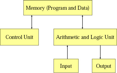
Two main computer architectures include the Von Newman Architecture and the Harvard architecture. The hypothetical 4917 from COMP1917 was a Von Newman Architecture because both the program and the data were stored in the same memory. (It seems that processors like the Intel Pentium 4, Intel Core 2, etc. use this architecture)

vonnewman

Another key thing is the Arithmetic and Logic Unit (ALU) and the Control Unit are collectively called the CPU (Central Processing Unit). A microprocessor is just a CPU on a single chip. A microcontroller is basically a computer on a chip, so the CPU, memory, etc. are all on a single chip.

I learnt a lot from experimenting with this architecture and the 4917 (and its successors). Though when I began to write more complex programs I found myself constantly putting a GOTO instruction number n command at the very begining, and using that skiped space as memory for data. I also came to see that this architecture allows for the buffer overflow vulnerability as program data can be executed as instructions if there are vulnerability. These two observations tend to lead to the Harvard architecture (which I am new to).

harvard

This is the architecture used for the Atmel AVR microprocessor, which is what we will focus on in this course (I think). I'll come back to this when I talk about address space.

Computer Memory

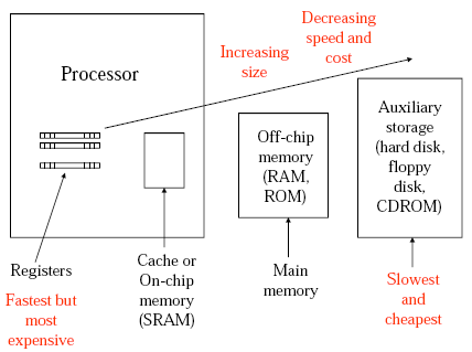
This is the computer memory hierarchy diagram from the lecture notes.

mem_hierarchy

This helps put a lot of my misunderstandings of how the 4917 from COMP1917 relates to modern processors, as I didn't quite see if the instructions and data were stored in RAM or on the CPU. But really this is just an implementation issue so it didn't really matter to the 4917.

In the CPU there are registers which are really fast, but there are few (apparently in x86 (eg. Pentium, Core 2) there are only 8 integer and 8 floating point registers). Then there is the cache (on chip memory), this is what that 4MB cache that I see advertised that my CPU has. This cache can be separated for program code and data. This is faster that reading from RAM (the off chip memory), so currently active program code is moved to here from the RAM when necessary to speed things up (this is apparently implemented on the hardware level (which is always nice for a software developer ;) ). Then there is off-chip memory and auxiliary storage. This fits in nicely with the picture I get when I open up my computer.

The material on the types of RAM and ROM in the lecture notes needs no further commentary, so I'll skip that part.

ISA (Instruction Set Architecture)

"ISA is the interface between hardware and software

This sums up the situation nicely, and makes perfect sense.

There are 4 things that make up memory instruction set architectures,

RISC - Reduced Instruction Set Computer CISC - Complex Instruction Set Computer

Atmel AVR is RISC.

Number Systems

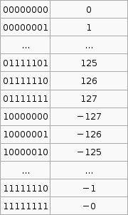
Problem: How do we represent negative numbers in a computer? 4 main methods (from Wikipedia).

ones_compliment

twos_compliment

It is important to know that the hardware does all arithmetic in 2's compliment. It is up to the programmer to interpret the number as signed or unsigned.

To convert a number from 2's compliment, for example -45 in 2's compliment is 11010011, we can do something like this,

$latex 1 \times (-2^7) + 1 \times 2^6 + 1 \times 2^6 + 0 \times 2^5 +1 \times 2^4 + 0 \times 2^3 + 0 \times 2^2 + 1 \times 2^1 + 1 \times 2^0 = -45$

To go the other way from say -1 to the 2's compliment form 11111111 we use that $latex 2^p - X$ formula. I'm not exactly sure how its supposed to work so I've hacked it to make it work.

If the number you wish to convert is negative, let $latex X = -n$, so that X is positive then take $latex 2^p$ where p is the number of bits you are using (say 8), then subtract X. If the number to convert is less than $latex 2^p$ (where p is the number of bits, say 8 ) then leave it as is and that in your 2's compliment.

Now that was complicated. But its the only way I can get that advertised $latex 2^p - X$ formula to work with the given set of sample data (as in that table above).

This raises an issue for comparison operations. eg. Is 1111 1100two > 0000 0010two? If those two numbers are unsigned then YES, if they are signed thin NO. As such the hardware uses the S flag in AVR to indicate the result of the signed comparison, and the C flag to indicate the result of unsigned comparison.

Representing Strings. We saw one method back in COMP1917 though its nice to see that the other methods that come to mind were used also.

  1. 1st position of string reserved for length (Pascal)
  2. an accompanying variable has the length of the string (as in a structure)
  3. last position of string marked with a special character (NULL in C)

Sign Extension

How do we extend a binary number of m bits to an equivalent binary number of m + n bits? If the number is positive add n 0's to the most significant side (usually left) of the binary number. If the number is negative add n 1's to the most significant side of the binary number. This is called sign extension. To add twe binary numbers of different lengths just sign extend the shorter one so that both numbers have the same bit length then add as usual.

References

Wu, Hui. COMP2121 09s1 Lecture Notes.

(Updated 20th June 2009 with explanation of 2's compliment conversions and sign extension)

Tags: comp2121, computing.

RSS Feed